|
The iPhone Wiki is no longer updated. Visit this article on The Apple Wiki for current information. |
Difference between revisions of "DCSD Cable"
P0sidonius (talk | contribs) (Created new page for DCSD hardware) |
(No difference)
|
Revision as of 03:53, 23 August 2016
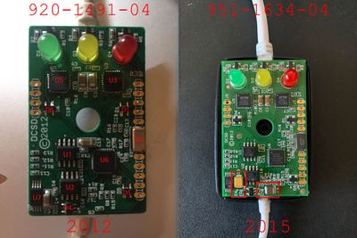
The DCSD Alex cable is used in factories to communicate over serial to run tests and write to the SysCfg (for serial definitions, etc) during production. These cables are produced by Shenzhen Alex connector Co. Ltd. in China, I believe this is why they can be found on obscure markets for sale, if not just taken from a trashcan from factories.
Factory DCSD "Alex" Lightning Serial Cable
Top of the board;
U1 / U2 - Micrel 2026A Dual-Channel Power Distribution Switch
X1 - MKC 24Mhz Oscillator
- Notes;
- I'm not 100% sure about the value of the chip, but this should be correct
U3 - FTDI FT232RQ UART IC
- Usage;
- Handles stoplight LED controls
- Datasheet; http://www.ftdichip.com/Support/Documents/DataSheets/ICs/DS_FT232R.pdf
U4 - Micrel MIC5219
- Description; 500mA-Peak Output LDO Regulator
- Datasheet; http://datasheet.datasheetarchive.com/originals/library/Datasheets-EDS7/DSAEDA000124178.pdf
U5 - FTDI FT232RQ UART IC
- Usage;
- Handles serial mux interface from iPhone
- Datasheet; http://www.ftdichip.com/Support/Documents/DataSheets/ICs/DS_FT232R.pdf
U6 - SMSC USB2514 4-port USB hub
- Datasheet; http://www.mouser.com/catalog/specsheets/2514.pdf
- Notes;
- The use of this deprecates the previous "Y" style cable, which used two separate USB cables for serial and iPhone data communication
- Three ports are used;
- iPhone Data USB
- U4 FTDI IC
- U5 FTDI IC
U7 - Microchip 24AA04/24LC04B
- Description; I2C Serial EEPROM(TSSOP Package)
- Datasheet; http://ww1.microchip.com/downloads/en/DeviceDoc/21708G.pdf
D1 / D6 / D5 - Torex XC6215
- Description; A Low Power Consumption Voltage Regulator with ON/OFF Switch
- Datasheet; http://www.s-manuals.com/pdf/datasheet/x/c/xc6215_series_torex.pdf
- Notes;
- D6 is tied to TX and an input voltage of 3.3v on the UART J5 pads, this may be a protection in case the host shorts?
Back of the board;
J11 / J10 / J9 / J12
- I believe these are used to flash the U7 EEPROM with USB IDs for use by the SMSC USB Hub, I have yet to dump the contents of the EEPROM to find out for sure.
Other notes;
- The lightning connector has a specific Accessory ID flashed to it for enabling serial via the Tristar chip.
- This PCB is quite easy to replicate, but without the proper Accessory ID you will need to mimic the protocol similar to how key2fr did in his research.
- In theory, you can use the Tristar for JTAG through a similar board, but JTAG gets enabled by the device during boot due to production fusing status.
