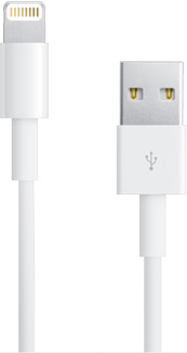
Lightning connector compared to USB

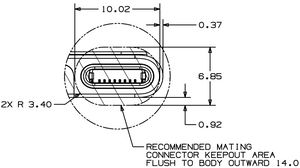
Lightning connector mechanical drawing (front)

Lightning connector from aerial, front, top, and socket angles
Lightning is the new connector of the iPhone 5 , iPad mini , iPad 4 and the 5th generation iPod touch. It was presented by Tim Cook at an Apple Special Event on September 12, 2012. Lightning matches up with the existing Thunderbolt branding as noted by Phil Schiller. According to Apple it as an all-digital connector and "features an adaptive interface that uses only the signals that each accessory requires and also is 80% smaller as well as orientation independent."
- Lightning is adaptive.
- All 8 pins are used for signals, and all or most can be switched to be used for power.
- The outer plug shell is used as ground reference and connected to the device shell.
- At least one (probably at most two) of the pins is used for detecting what sort of plug is plugged in.
- All plugs have to contain a controller/driver chip to implement the “adaptive” thing.
- The device watches for a momentary short on all pins (by the leading edge of the plug) to detect plug insertion/removal.
- The pins on the plug are deactivated until after the plug is fully inserted, when a wake-up signal on one of the pins cues the chip inside the plug. This avoids any shorting hazard while the plug isn’t inside the connector.
- The controller/driver chip tells the device what type it is, and for cases like the Lightning-to-USB cable whether a charger (that sends power) or a device (that needs power) is on the other end.
- The device can then switch the other pins between the SoC’s data lines or the power circuitry, as needed in each case.
- Once everything is properly set up, the controller/driver chip gets digital signals from the SoC and converts them – via serial/parallel, ADC/DAC, differential drivers or whatever – to whatever is needed by the interface on the other end of the adapter or cable. It could even re-encode these signals to some other format to use fewer wires, gain noise-immunity or whatever, and re-decode them on the other end; it’s all flexible. It could even convert to optical.
Pinnout
Top (DHC marked)
| Pin
|
Signal
|
Description
|
| 1
|
V-
|
|
| 2
|
D+
|
|
| 3
|
D-
|
|
| 4
|
(dynamic)
|
|
| 5
|
(dynamic)
|
|
| 6
|
(dynamic)
|
|
| 7
|
(dynamic)
|
|
| 8
|
(dynamic)
|
|
Bottom
| Pin
|
Signal
|
Description
|
| 8
|
V-
|
|
| 2
|
D+
|
|
| 3
|
D-
|
|
| 1
|
(dynamic)
|
|
| 4
|
(dynamic)
|
|
| 6
|
(dynamic)
|
|
| 7
|
(dynamic)
|
|
| 5
|
(dynamic)
|
|
USB
| Pin
|
Signal
|
Description
|
| 1
|
V+
|
|
| 2
|
D-
|
|
| 3
|
D+
|
|
| 4
|
V-
|
|
External Resources

|
This hardware article is a "stub", an incomplete page. Please add more content to this article and remove this tag.
|


